Category
Figure Listing
Diagram
-- Select Diagram --
1.0 Frame and floor
10.0 Tandem axle assy 16t
11.0 Brake axle cpl. FAD, 16t
12.0 Air pressure brake fitting
13.0 Air pressure brake fitting
14.0 Air pressure brake fitting
15.0 Air pressure brake fitting
16.0 Air pressure brake fitting
17.0 Air pressure brake fitting
18.0 Tyres
19.0 Mudguard
2.0 Conveying floor
20.0 Drawbar hitch
21.0 Drawbar
22.0 Support jack
23.0 Pick-up
24.0 Pick-up suspension
25.0 Pick-up cpl.
26.0 Lateral supporting wheel (pneumatic)
26.1 Supporting wheel back
27.0 Hydraulic - pick-up lift
28.0 Feed drum
29.0 Gearbox
3.0 Hydraulic assistance
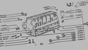
30.0 Gearbox
31.0 Conveyor channel
32.0 Cutting mechanism
33.0 Hydraulic cutting mechanism XL-Baureihe
34.0 Gearbox front
35.0 Gearbox front
36.0 Front guard GD
37.0 Metering roller drive
38.0 Gearbox back
39.0 Metering rollers
4.0 Gearbox cpl.
40.0 Rear drive
41.0 Metering roller shift mechanism
42.0 Guard
43.0 Superstructure bottom
44.0 Inspection door assembled
45.0 Super structure (Above)
46.0 Automatic scraper floor control
47.0 Tarpaulin
48.0 Hydraulic Wall return
49.0 Electric comfort control unit
5.0 Tandem axle assy 11,2 t
50.0 Lighting 80 km/h
51.0 Lighting
52.0 Wiring harness
53.0 Wiring harness
54.0 Wiring harness
54.2 Control bloc
54.3 Hydraulic for comfort-control
55.0 P.T.O shafts -Walterscheid
55.1 P.T.O shafts -Walterscheid
55.2 P.T.O shafts W2400-285
56.0 Warning signs
57.0 General information labels
6.0 Brake axle cpl. ADR, 11,2 t
7.0 Brake axle cpl. FAD, 11,2 t
8.0 Brake axle cpl. ADR, 16t
9.0 Hydraulic brakes
Prev
Next
Print PDF
Copy Link