







Kubota BX1880, BX2380, BX2680 Engine Start System Check
Tags : bx-maintenance | kubota-bx1880 | kubota-bx2380 | kubota-bx2680 | safety-switch | starting-system |BX1880 / BX2380 / BX2680 Owner Service Guide
The engine will not crank unless the speed control pedal is in neutral and the PTO clutch lever is off. A safety switch on each of those controls opens the starter circuit when the control is out of position. Kubota calls for checking both switches every 50 hours. The check takes about five minutes, is done from the seat, and needs no tools or parts.
| Interval | Every 50 hours |
|---|---|
| Time | 5 minutes |
| Tools | None |
| Parts | None |
How the start interlock works
When the key is turned to START, current flows from the battery through the safety switches to the starter relay. The HST neutral switch is a plunger switch mounted on the speed control pedal linkage. It is closed only when the pedal is in neutral. The PTO switch and PTO shift lever switch are the same type of plunger switch, mounted on the PTO lever linkage and closed only when the lever is in the OFF position. If any of these switches is open the starter does not receive current. The seat switch is also in the circuit but is part of the operator presence control system and is covered by the OPC system check.
The test puts one control out of position at a time and confirms the engine does not crank. If the engine cranks, the switch for that control, its adjustment, or its wiring has failed.
Preparation
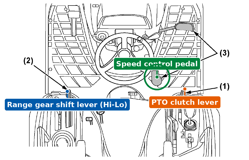
- Sit in the operator's seat and remain seated for the entire test. The seat switch must be closed so that only the pedal and PTO switches are being tested.
- Set the parking brake and turn the key to OFF.
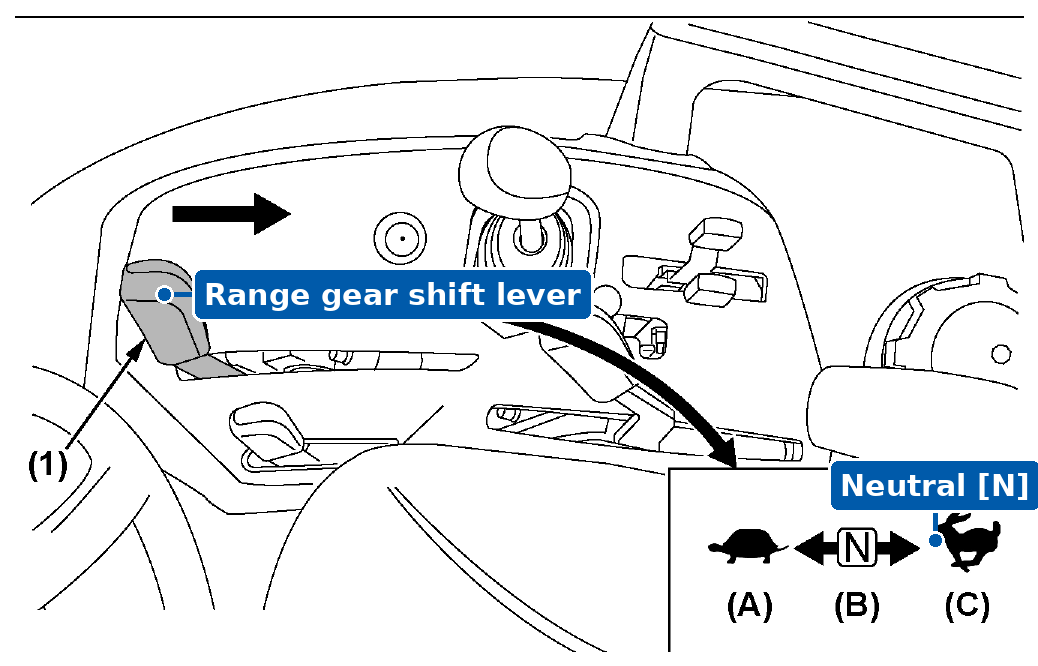
- Move the range gear shift lever on the left side of the seat to neutral [N]. Neutral is the center position between Low and High.
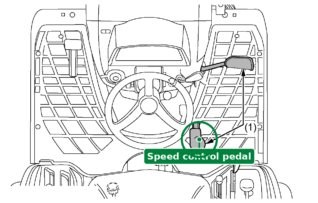
- Take your foot off the speed control pedal. The pedal is spring-loaded and returns to neutral on its own. If it does not return, correct that first. See HST neutral spring adjustment.
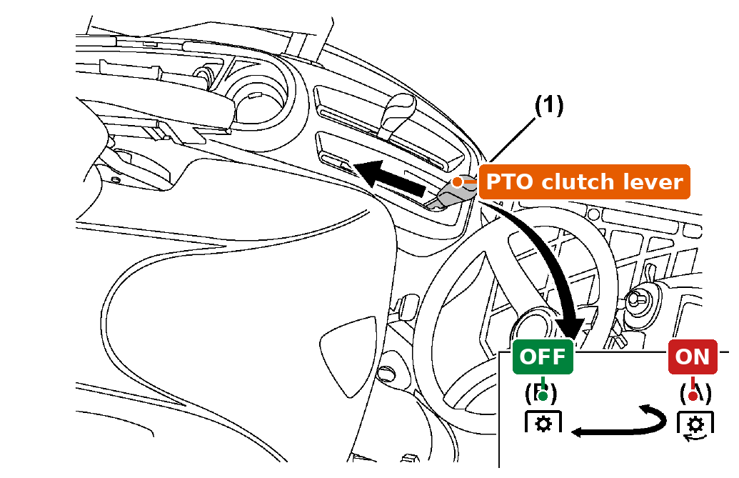
- Move the PTO clutch lever on the right side of the seat forward to the OFF position.
Test 1: speed control pedal switch
- Confirm the range gear shift lever is in neutral and the PTO clutch lever is OFF.
- Press the speed control pedal and hold it down. Either forward or reverse is acceptable.
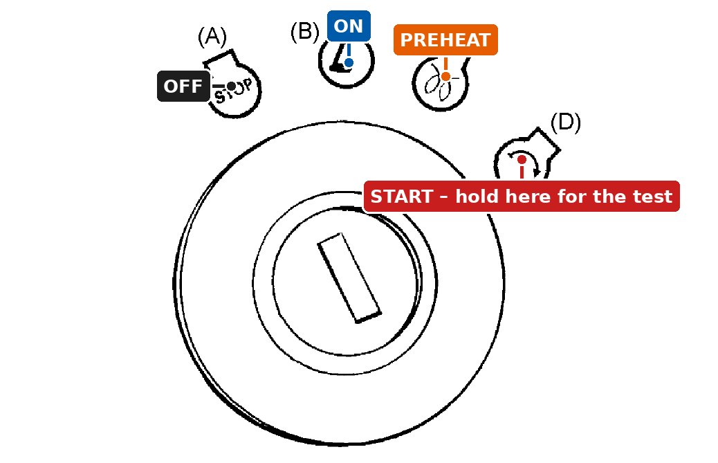
- Turn the key to START and hold it for one to two seconds.
- The engine must not crank.
- Release the key to OFF, then release the pedal.
Test 2: PTO clutch lever switch
- Confirm the range gear shift lever is in neutral and the speed control pedal is in neutral.
- Pull the PTO clutch lever rearward to the ON position.
- Turn the key to START and hold it for one to two seconds.
- The engine must not crank.
- Release the key to OFF, then return the PTO clutch lever to OFF.
When both tests pass, the check is complete. Record the hour meter reading. The grease fittings are on the same 50-hour interval and are normally done at the same time.
Failed test
A failed test means the starter received current with a control out of position. There is no owner adjustment for this condition. Kubota's instruction is to stop using the tractor and contact the dealer. The causes, in the order they are normally checked:
| Failed test | Cause | Part |
|---|---|---|
| Test 1 (pedal pressed, engine cranks) | HST neutral switch stuck closed, out of adjustment, or the pedal linkage is not releasing the plunger | Safety switch K2871-62250 |
| Test 2 (PTO on, engine cranks) | PTO switch or PTO shift lever switch stuck closed or out of adjustment | Safety switch K2871-62250 |
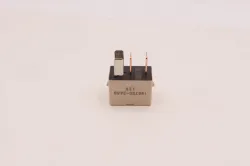
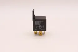
| Either test | Damaged harness or a bridged connector bypassing the switch; starter relay contacts stuck closed | Relay K3181-62330 |
Engine does not crank with the controls in position
If the controls are in neutral, the PTO is off, the operator is seated, and the starter does not operate, the fault is in the same circuit. Check the following in order before replacing a switch.
- Battery. A discharged or failed battery is the most common cause. See Battery check.
- 50 A slow-blow fuse at the battery. A blown slow-blow fuse disables the entire starting circuit. Slow-blow fuse K2771-63910. See Fuse replacement.
- 15 A stop solenoid fuse. If this fuse is blown, the stop solenoid does not energize and the starter will not operate. 15 A mini fuse T1060-30450. A fuse puller clips into the fuse box cover.
- Safety switches open when they should be closed. Common reasons are a pedal not fully returning to neutral, a PTO lever not fully in OFF, a worn plunger, or incorrect switch clearance. Move the pedal and the PTO lever through their positions while a second person turns the key.
- Seat switch not closing. The seat must be fully down. Seat switch K1122-62280.
- Key switch, starter relay, stop solenoid, and starter motor.
Switch locations and testing
The rear wheels must be removed to reach the switches.
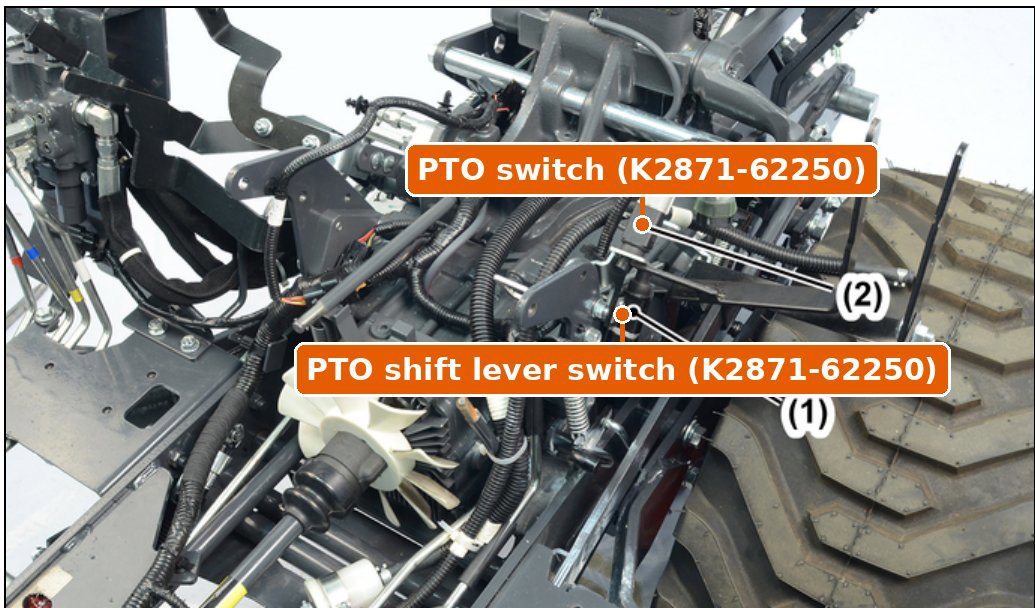
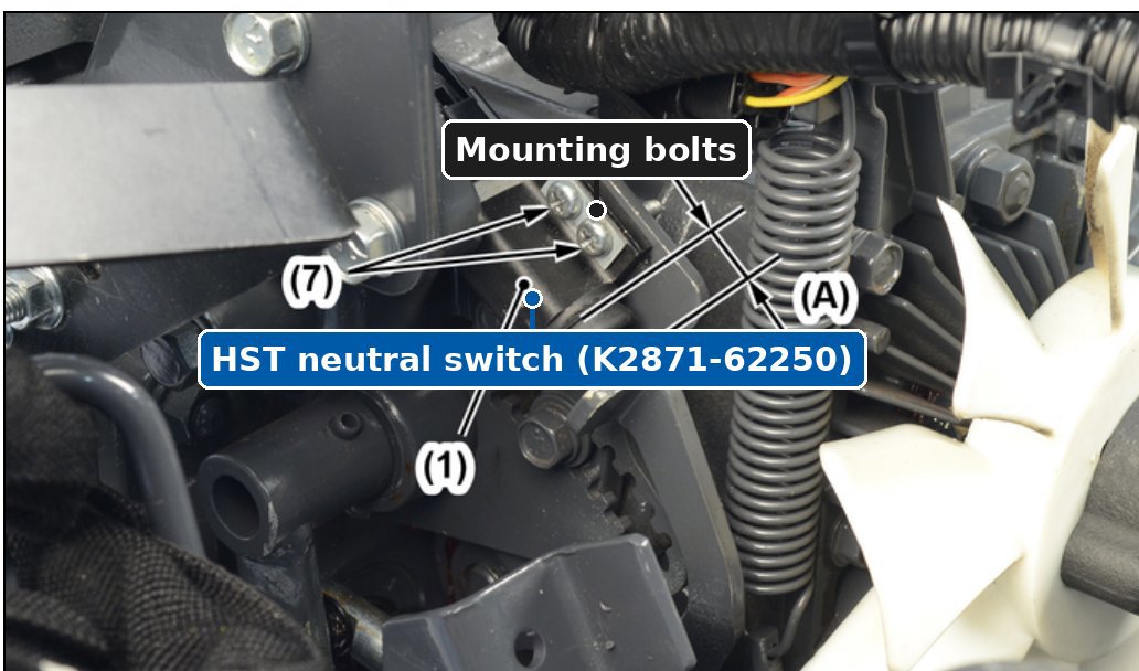
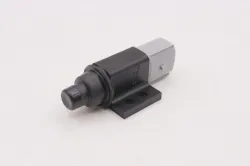
The PTO switch and PTO shift lever switch are behind the left rear wheel on the PTO lever linkage. The HST neutral switch is behind the right rear wheel on the pedal linkage, next to the neutral return spring. All three are the same part, K2871-62250, a normally open, two-contact, waterproof plunger switch.
Continuity test
- Support the tractor on stands, remove the wheel, and unplug the switch connector.
- Remove the switch from its bracket.
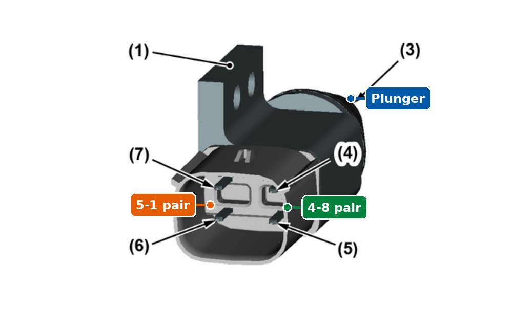
- Measure resistance across terminals 4 and 8, then across terminals 5 and 1. The terminal numbers are molded into the connector.
- With the plunger pushed in, both pairs must read 0 Ω.
- With the plunger released, both pairs must read infinity.
- Any other reading indicates a failed switch. Replace it.
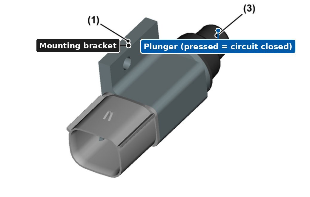
Installation
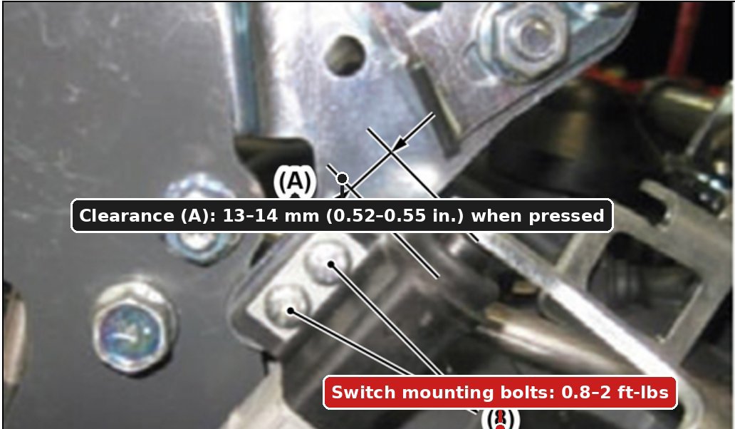
Mount the switch so that the clearance (A) between the switch body and the actuating plate is 13 to 14 mm (0.52 to 0.55 in.) with the switch pressed. Tighten the mounting bolts to 0.8 to 2 ft-lbs. The same clearance and torque apply to all three switches.
Seat switch
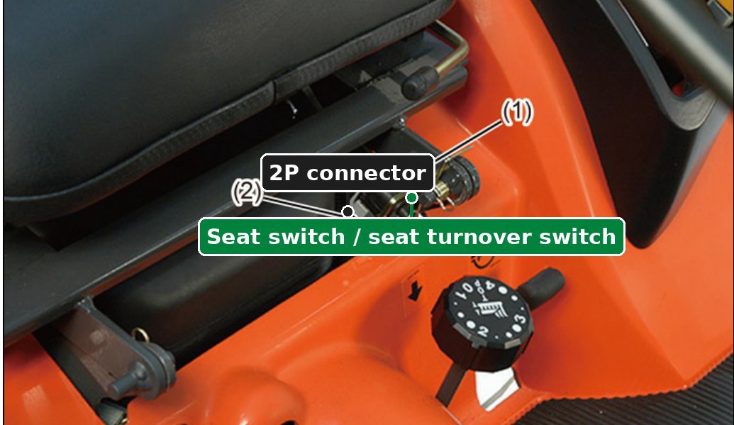
For a no-crank condition, also check the seat switch and seat turnover switch under the seat cushion. Unplug the two-pin connectors and measure across the switch terminals. The switch must read open with the seat unoccupied and 0 Ω with the seat pressed down. Seat switch K1122-62280.
Circuit description
With the key in PREHEAT, the glow plugs are energized and the preheat lamp is on. With the key in START and all safety switches closed, the starter relay energizes the starter motor. When the key is released it returns to ON and the start circuit opens. Turning the key to OFF de-energizes the stop solenoid, which moves the injection pump rack to the no-fuel position and stops the engine. The OPC timer stops the engine approximately one second after the operator leaves the seat with the PTO engaged or the tractor in gear.
Parts
No parts are required for the check. These are the parts in the starting circuit.
| Part | Part number | Notes |
|---|---|---|
| Safety switch (HST neutral, PTO, PTO shift lever) | K2871-62250 | Three per tractor |
| Seat switch | K1122-62280 | |
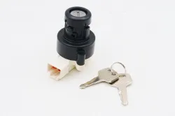
| Key switch assembly | K2871-62100 | |
| Key | TC832-31810 | |
| Relay | K3181-62330 | BX2380 serial 42226 and up: diagram B21302 |
| Relay, 20 A | K7311-62310 | OPC |
| OPC timer | TD060-30500 | Under the upper panel |
| Timer | 1J321-60242 | Stop solenoid timer relay |
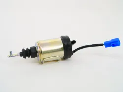
| Stop solenoid | 1J025-60012 | |
| Slow-blow fuse, 50 A | K2771-63910 | At the battery |
| Mini fuse, 15 A | T1060-30450 | Stop solenoid |
| Mini fuse, 5 A | T1065-30430 | OPC |
| Fuse puller | K2883-63380 | |
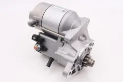
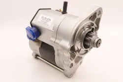
| Starter, BX1880 and BX2380 | 19269-63010 | Remanufactured: 77700-06123, core charge applies |
| Starter, BX2680 | 1G324-63010 |
Parts catalogs: BX1880, BX2380, BX2680.
Related
- OPC system check
- Battery check
- Fuse replacement
- HST neutral spring adjustment
- BX Owner Service Guide
To have the test or the repair done at Messick's, schedule service.








More Articles